VSC Screw Compressor Vibration Analysis Case Study
VSC received data on a screw compressor as part of our Remote Vibration Monitoring Program. It is not unusual for screw compressors to have higher vibration than most other industrial equipment due to the basic nature of the machine. The way to analyze any machine problem is by diagnosing the specific frequencies the data reveals.
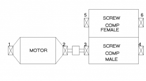
Figure 1: Screw Compressor Drawing
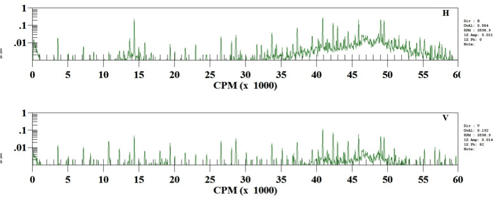
Most screw compressors have sleeve bearings, but they often also have thrust bearings that are roller bearings. If these thrust bearings wear and fail, they will cause a catastrophic failure of the machine. Vibrational analysis is a great way to detect these problems. Figures 2 and 3 are the low and high frequency vibration spectra for the inboard female lobe bearings that show a raised noise floor with harmonics of the bearing frequency running across the spectra. This type of signature is a strong indicator of a looseness condition.
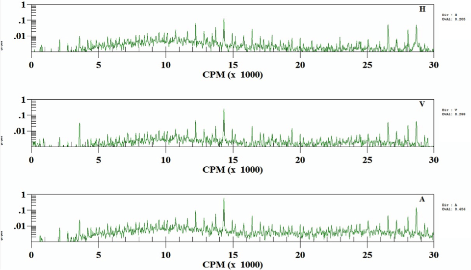
Figure 2: Inboard Female lobe bearing low frequency spectra
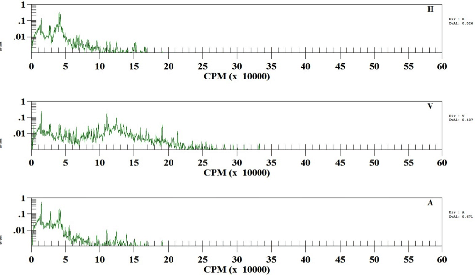
Figure 3: Inboard Female high frequency spectra
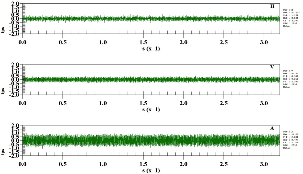
Figures 4 below shows the high frequency time waveform data from the inboard female bearing that has peak-to-peak levels up to 2.0 inches per second (ips) of vibration. Figure 4: IB Female High Frequency time waveform data
Figures 5 and 6 are the low and high frequency spectra from the inboard male bearing which show the same looseness condition and raised noise floor as the inboard female bearing. Figure 5: Inboard Male low frequency spectra
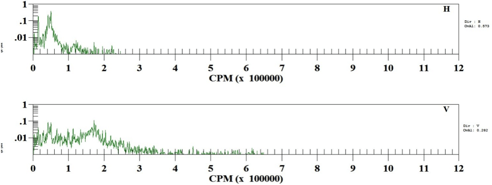
Figure 6: IB Male High Frequency Spectra
The time waveform from the male lobe inboard bearing in figure 7 has peak to peak levels over 2.0 ips, while figure 8 has peak-to-peak acceleration levels up to 47 g’ of acceleration. Both of these sets of data expose the impacting that comes from worn roller bearings.
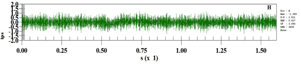
Figure 7: Inboard Male high frequency waveform
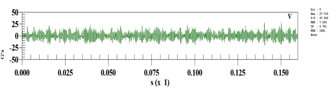
Figure 8: IB Male low frequency waveform
It is always important to compile as much data as possible to help corroborate your analysis. Therefore, we employed the envelope readings which confirmed the findings of the spectra and waveform analysis. Below, in figure 10, the envelope spectrum has a DC level of 1.45 g’, indicating bearing wear.
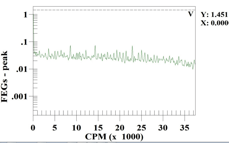
Figure 10: Inboard Male Envelope spectrum
In the case of this screw compressor, the thrust bearings are located on the inboard side of the male and female lobes, which is why we found the highest vibration readings on these inboard bearings. When you engage in a periodic vibrational analysis monitoring program on your machinery, it really exposes the health of the equipment so you can proactively schedule your repairs when it is best for your operations. The world is changing quickly and maintenance is rapidly accepting predictive maintenance and machine condition monitoring because it is clearly the preeminent way to conduct maintenance because of the dramatic 10 to 1 return on investment it provides.